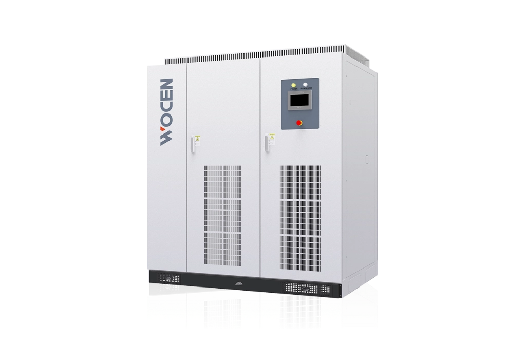
HomeProductsDC Test Power SupplyBidirectional DC Test Power SupplyBidirectional DC Test Power Supply

Bidirectional DC Test Power Supply

WB5000 Series

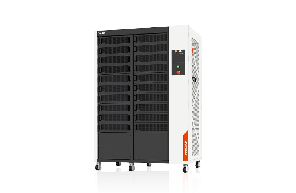
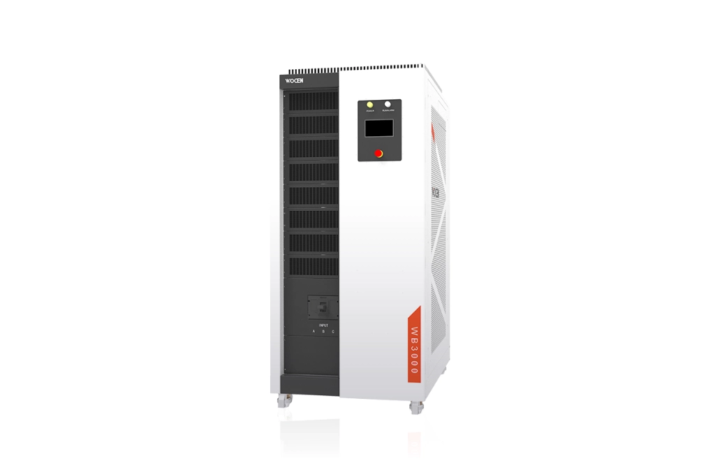
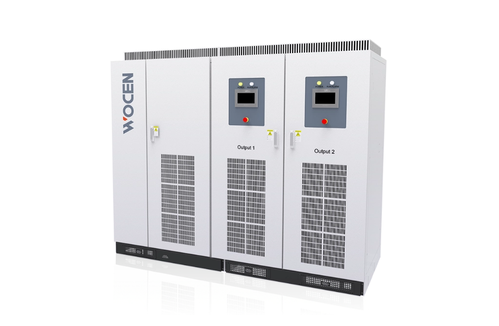
The WB5000 Series is designed for R&D and testing across a wide range of applications, including electric vehicle (EV) drive motors, EV powertrain systems, DC charging stations, and energy storage converters.

Built with the latest third-generation wide-bandgap SiC semiconductor technology, the WB5000 Series is optimized for high-frequency operation, modularity, standardization, and high performance. It is a high-quality bidirectional DC power supply that combines high precision, fast dynamic response, and high efficiency.

Voltage Accuracy

±0.02%F.S

Current Accuracy

±0.02%F.S

Response Time

500μs

Switching Time

1ms

Share:

  • Product Description

  • Product Features

Key Advantages

  • 01
    Third-Generation SiC Technology

    Designed with advanced third-generation wide-bandgap SiC semiconductor devices for stable and reliable operation.

  • 02
    Fast Transient Response

    Transient response time of ≤500 μs.

  • 03
    High-Frequency Modular Design

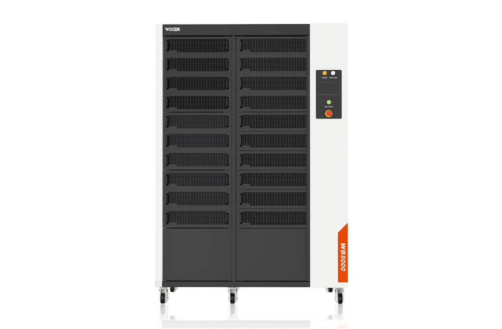
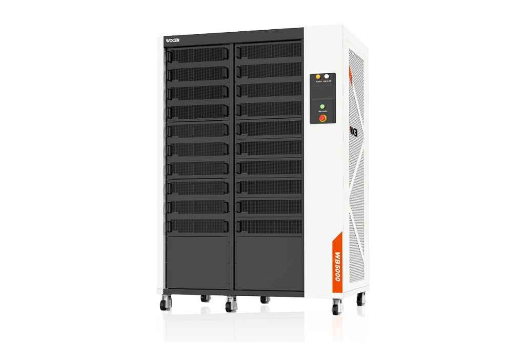
    Power modules feature a high-frequency modular design with drawer-type installation, making maintenance and module replacement easier.

  • 04
    High Efficiency

    Efficiency of >95%, delivering significant energy savings and reduced power consumption.

  • 05
    High-Precision Digital Control

    Advanced high-speed digital control technology enables output accuracy of up to 0.02% F.S.

  • 06
    Low Harmonic Distortion

    PWM rectification technology delivers a power factor >0.99 and output THD <3%.

  • 07
    Built-In Battery Simulation Models

    Includes 5 built-in battery characteristic curves, such as LiFePO₄, NMC, and LMO, with support for 5 user-defined battery characteristic curves.

  • 08
    7-Inch Touchscreen

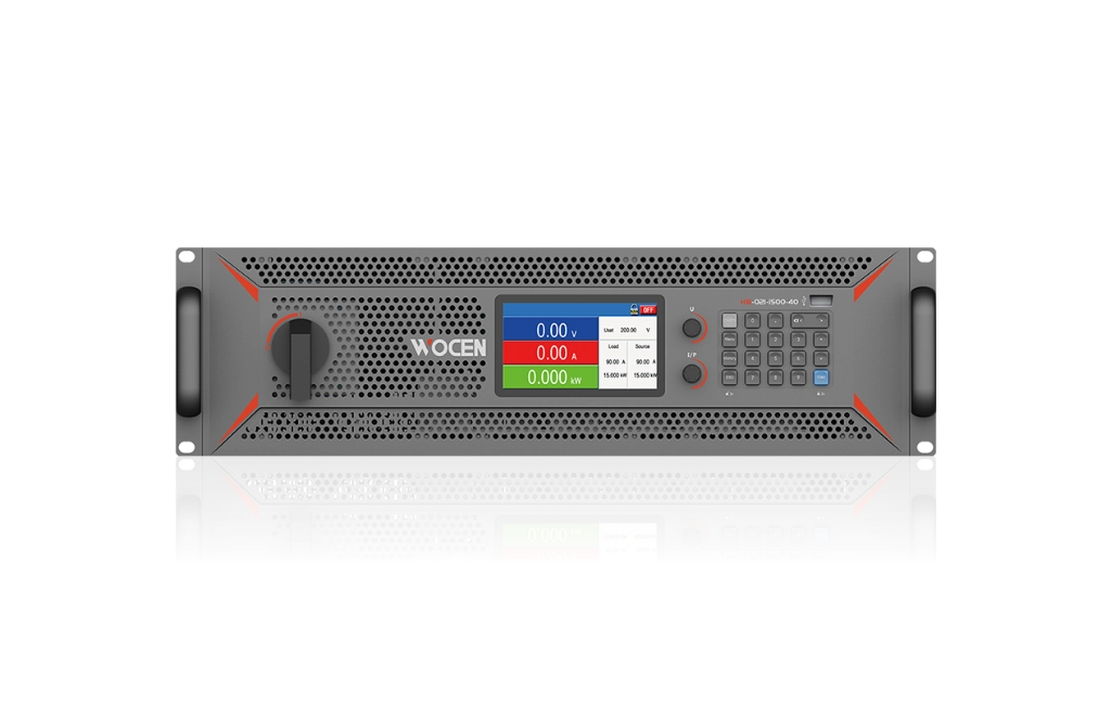
    A 7-inch touchscreen provides intuitive operation and convenient real-time display.

Models & Specifications

Model
Rated Power
Output Voltage
Rated Current
Size (WDH)
WB5100-1200-300
100KW
20~1200V
±300A
850*1000*1500
WB5200-1200-600 200KW
20~1200V
±600A
850*1000*1500
WB5300-1200-900 300KW
20~1200V
±900A
850*1000*2000
WB5400-1200-1200 400KW
20~1200V
±1200A
1650*1000*2000
WB5500-1200-1200 500KW
20~1200V
±1200A
1650*1000*2000
WB5600-1200-1200 600KW
20~1200V
±1200A
1650*1000*2000

Technical Specifications

Category

Item

Value

Output Parameter

Voltage Accuracy

±0.02%F.S

Current Accuracy

±0.02%F.S

Response Time

500μs

Switching Time

1ms

Voltage Slew Rate

300V/ms

Current slew rate

500A/ms

Voltage Ripple

≤0.1%F.S

Current Ripple

≤0.1%F.S

Input Parameter

Input Mode

3-phase 3-wire + PE (3L+PE)

Voltage

AC 380V±15%

Frequency

47-63Hz

Power Factor

≥0.99

Current THD

≤3%

Security features

Insulation Resistance

≥20MΩ(500VDC)

Hstand Voltage Performance

3000Vdc rms(60s, no arcing or breakdown)

Grounding Resistance

≤100mΩ

Communication interface

RS485, Ethernet, CAN

Protection grade

IP21(indoor use)

Cooling mode

Forced air cooling

Working environment

Ambient Temperature

-10℃~45℃

Ambient Humidity

10%~90%(non-condensing)

Altitude

≤2000m

Notes

Tested at rated input voltage and current; harmonic RMS values within full power range shall not exceed the absolute value at rated conditions.

Optional Functions

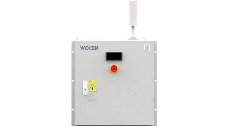
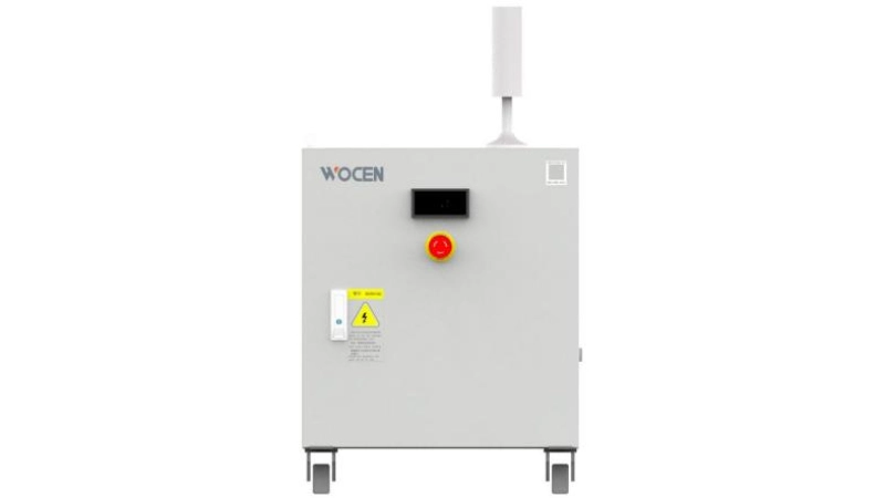
1.PDU (Power Distribution Unit / Wiring Box)

The PDU is a wiring box installed near the motor controller system, serving as the connection interface between the system under test and the battery simulator.

PDU-Wall-mounted

PDU-Upright type


- Built-in DC Input and Output Busbars: Equipped with internal DC input and output copper busbars to facilitate wiring and cable replacement. The busbar specifications meet the requirements for continuous operation at rated current.

- Power-On Indicator: An indicator light is installed on the top of the enclosure. It illuminates when the battery simulator is operating, warning users that high voltage is present inside the PDU and that there is a risk of electric shock.

- Voltage Display: Equipped with a voltage meter to display the real-time DC voltage.

- Door Interlock Protection: Equipped with a door safety interlock switch. When the PDU door is opened, the signal triggers the corresponding relay circuit in the battery simulator, causing the power supply to shut down.

- Emergency Stop Button: An emergency stop button is installed on the PDU door. Pressing it immediately stops the DC output of the battery simulator.

- Installation and Cable Routing: Available in floor-standing and wall-mounted configurations, with bottom-entry and bottom-exit cable routing.

2.Discharge cabinet

Bleeder Resistor Model

Power Supply Rating

Resistor Model

Number of resistors

Peak Dissipation Power (800V/1000V/1200V)

EVWB-DCU-1

0K-200K

2.5Ω/260kW-3S

1

260kW

EVWB-DCU-2

201K-500K

2.5Ω/260kW-3S

2

520kW

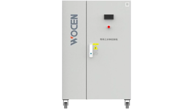
Discharge cabinet

- Discharge Activation Conditions: The discharge circuit is activated when an alarm occurs during DC power supply operation or when the power supply shuts down normally without a fault.

- Connection Between the Discharge Resistor and Power Supply: The connections include: ① Positive and negative output power cables; ② Discharge activation control cable; ③ Discharge activation feedback cable.

- Operating Principle: The positive and negative terminals of the discharge resistor are connected to the corresponding positive and negative terminals of the power supply's final output. A thyristor (SCR) is used as the switching device to control discharge activation inside the discharge resistor enclosure. When the specified trigger conditions are met, the power supply sends a discharge activation command to initiate the discharge process.


3.Capacitor Cabinet

To meet customers' stringent requirements for voltage fluctuation control during load-up and load-down processes, a capacitor cabinet is incorporated into the system design. The capacitor cabinet is detachable for easy removal and installation.

Capacitor Cabinet

EVWB-DRG-10000μF

(250 kW and below)

EVWB-DRG-20000μF

(Above 250 kW)

Rated Capacitance

10000μF

20000μF

Rated Voltage

1200V

1200V

Rated Current

1200A

1200A

Copper Busbar Current-Carrying Capacity

≥1200A

≥1200A

Enclosure Dimensions

700*580*620(Excluding Casters)

700*580*1000(Excluding Casters)

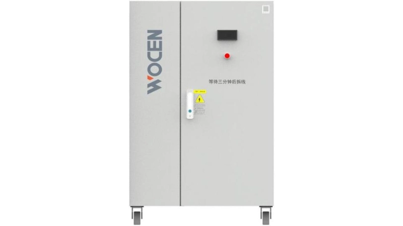
Capacitor cabinet

- Enhanced Voltage Stability: The capacitors in the capacitor cabinet supplement the internal capacitance of the power supply, significantly improving output voltage stability.

- DC Voltage Meter: Equipped with a DC voltmeter to display the voltage on the internal copper busbars in real time.

- Live Voltage Indicator: Equipped with a high-voltage safety indicator. When the busbar voltage exceeds 24 V (adjustable), the indicator lights up to enhance operational safety.

- Easy Mobility: Fitted with casters for convenient movement.

- Cooling System: Equipped with cooling fans inside the cabinet to ensure effective heat dissipation.


4.Insulation Monitoring

The insulation monitoring function supports both positive-to-ground and negative-to-ground insulation detection. By measuring the insulation resistance between the positive/negative terminals and ground, the system monitors the insulation condition of the power supply and the device under test (DUT) in real time.

When the insulation condition of the power supply or DUT falls below the specified requirements, the power supply sends a warning signal to the host computer. The customer's host computer then determines whether to issue a shutdown command to disconnect the power supply from the DUT and trigger an alarm, ensuring operator safety.

The insulation monitoring function can be enabled or disabled through software control. If insulation monitoring is not required, this function can be turned off.

Applications

  • Electric Vehicle Motor Testing 

  • Electric Vehicle Motor Controller Testing

  • Electric Vehicle Powertrain Testing 

  • Electric Vehicle Testing 

  • Electric Vehicle DC-DC Converter Testing 

  • Hybrid Vehicle Generator Testing 

  • Fuel Cell System Testing 

  • Fuel Cell DC-DC Converter Testing 

  • EV Charging Station Testing 

  • Battery Testing

Product Features

Bidirectional DC Power Supply Operation

Supports bidirectional energy flow across the full power range. Provides Constant Voltage (CV), Constant Current (CC), and Constant Power (CP) operating modes, with user-defined voltage, current, and power parameters.

Battery Simulation

1. Battery Type Mode
Users can select from five battery types: LMO, LCO, LiFePO₄, NMC, and Lead-Acid. Battery parameters including the number of cells in series, parallel configuration, and initial SOC can be configured. The I-V curve can be previewed before starting the simulation.

2. Custom Battery Mode
Users can define battery characteristics and create customized I-V curves. Up to 5 custom I-V curve profiles can be stored and recalled for testing when required.

During battery simulation, the system can dynamically plot the I-V curve based on SOC changes while displaying the current SOC, charge/discharge status, output voltage, output current, and output power in real time.

DC Programming Function

Supports two programming modes: Step and Ramp. Each mode allows up to 10 programmable sequences, with each sequence containing up to 50 sets of data.

Emergency Stop Function

Supports both local and external emergency stop controls. In emergency situations, such as motor runaway, the power output can be stopped immediately by pressing the emergency stop button on the control panel or activating an external emergency stop signal, helping prevent damage to the customer's equipment.

Line Voltage Compensation

Software-based compensation allows users to set the output cable impedance. The system automatically compensates the output voltage according to the configured line resistance value.

Self-Discharge Function

Self-Discharge OFF:
After receiving a stop command, the power supply maintains the current output voltage and quickly disconnects the output.

Self-Discharge ON:
After receiving a stop command, the power supply does not disconnect immediately. Instead, it rapidly reduces the output voltage to a safe level before disconnecting the output, improving operational safety.

Self-Diagnostic & Protection Functions

Provides comprehensive protection functions, including input phase-loss, overvoltage and undervoltage protection; DC bus overvoltage and undervoltage protection; output overvoltage, undervoltage, overcurrent, overheating, and short-circuit protection; and IGBT overcurrent protection.

The system continuously monitors key operating parameters, automatically diagnoses abnormal conditions, and rapidly disconnects the main circuit to help prevent damage to internal components.

Communication Functions

Standard communication interfaces include RS485, Ethernet, and CAN. The power supply can be connected to a PC for remote operation, unattended testing, and integration into automated test systems.

Through the communication interfaces, users can start and stop the power supply, configure operating parameters, and monitor operating status, parameter values, and alarm information in real time. DBC files are available for CAN communication integration.

Black Box Function

The built-in Black Box function automatically records electrical parameters before and after an alarm event, providing reliable data for fault analysis and troubleshooting.

Pre-Alarm & Parameter Limit Settings

Users can configure upper and lower pre-alarm limits for voltage, current, and power. When preset thresholds are reached, the system provides pre-alarm notifications, allowing users to customize the alarm parameters according to specific test requirements.

Output Parameter Limits

Upper limits can be configured for output voltage, output current, and output power settings. Users can modify these limits according to their requirements, helping prevent equipment damage caused by incorrect operation during different testing stages.

Temperature Monitoring

The system continuously monitors the operating temperature of key components, such as SiC modules and reactors, providing real-time temperature monitoring to ensure safe and stable operation.

Intelligent Fan Speed Control

Based on the temperature of internal key components, the cooling fans automatically switch between off, half-speed, and full-speed operation. This helps reduce operating noise while improving overall energy efficiency.

DC High-Voltage Output Relay Control

The DC output is controlled by a relay, enabling convenient remote control of the power supply with simple and flexible operation.

Parallel Operation

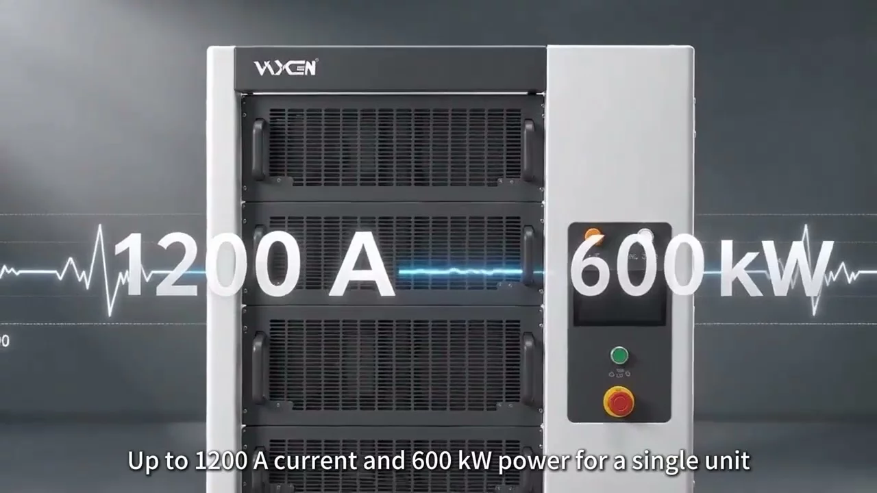
Supports flexible parallel connection of multiple units of the same model, enabling power configurations from 100 kW to 600 kW to meet different high-power testing requirements.

FAQ


lf your questions are not answered in the below list, please contact us.

Product Videos


Discover Product Features in Action.

Download


Product Information Document Downloads
WhatsApp

Leave a message!

Leave a message!