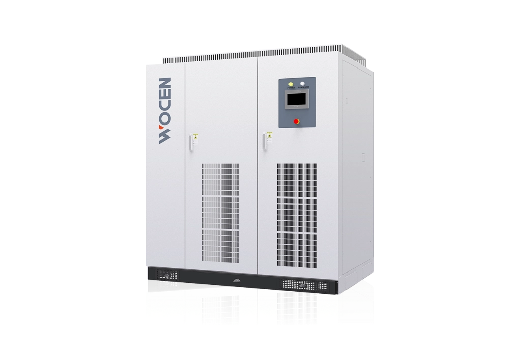
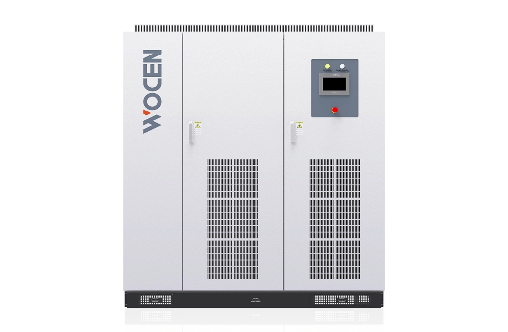
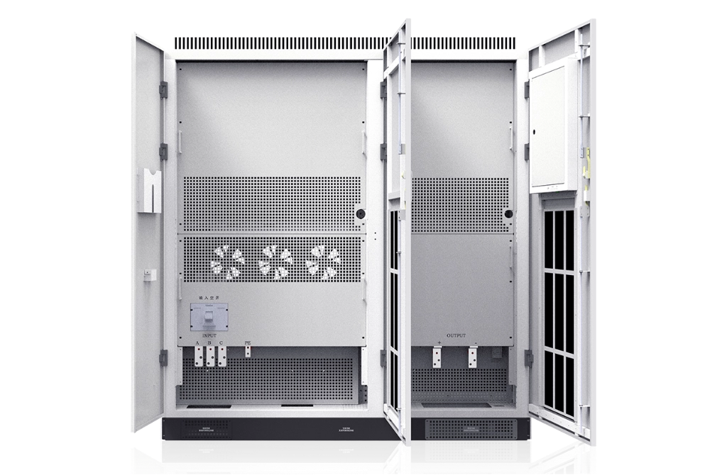
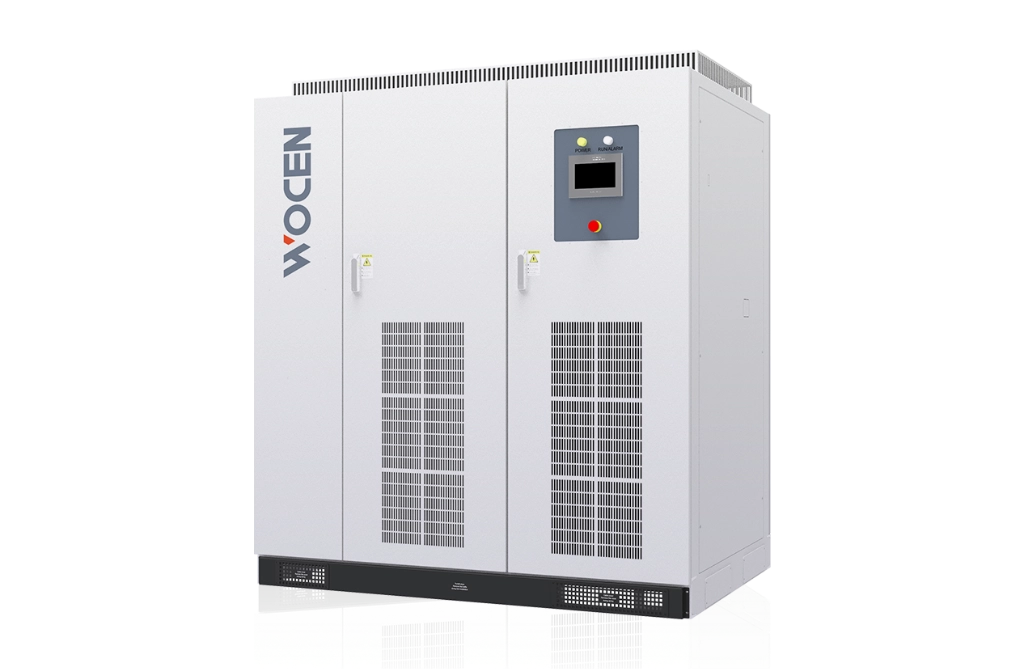
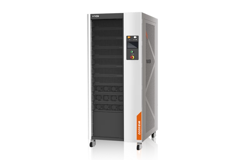
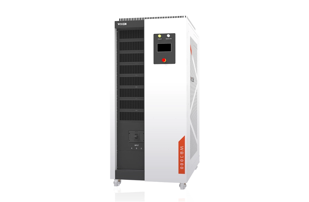
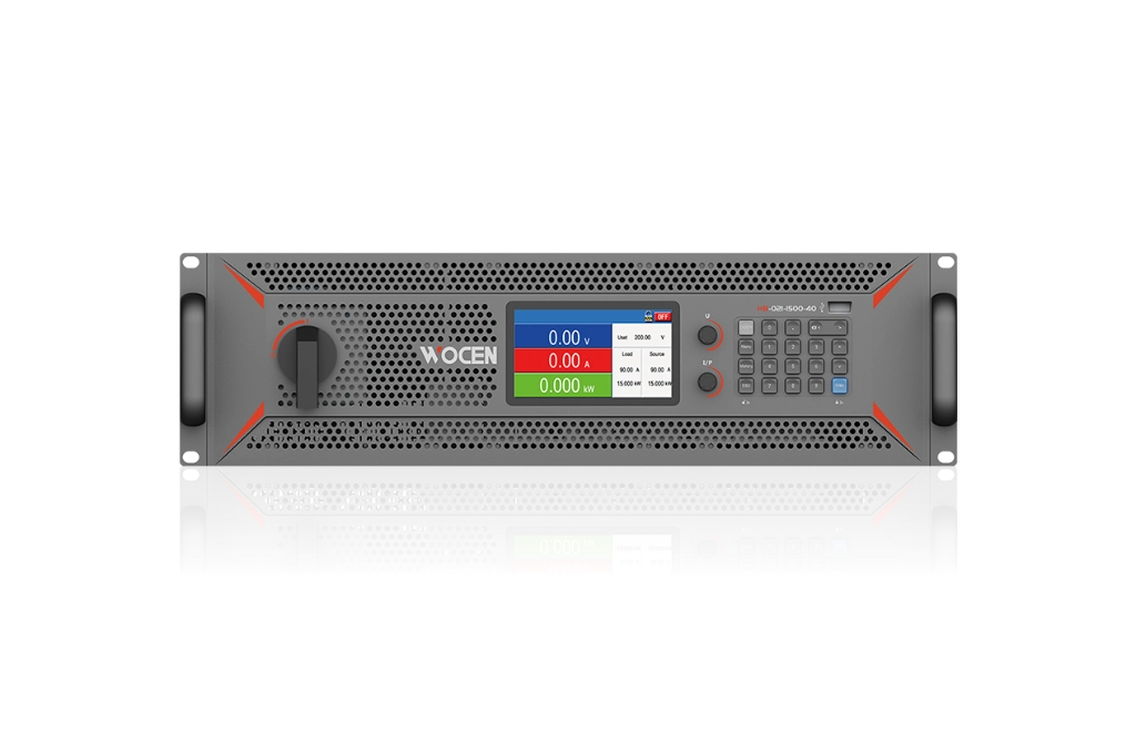
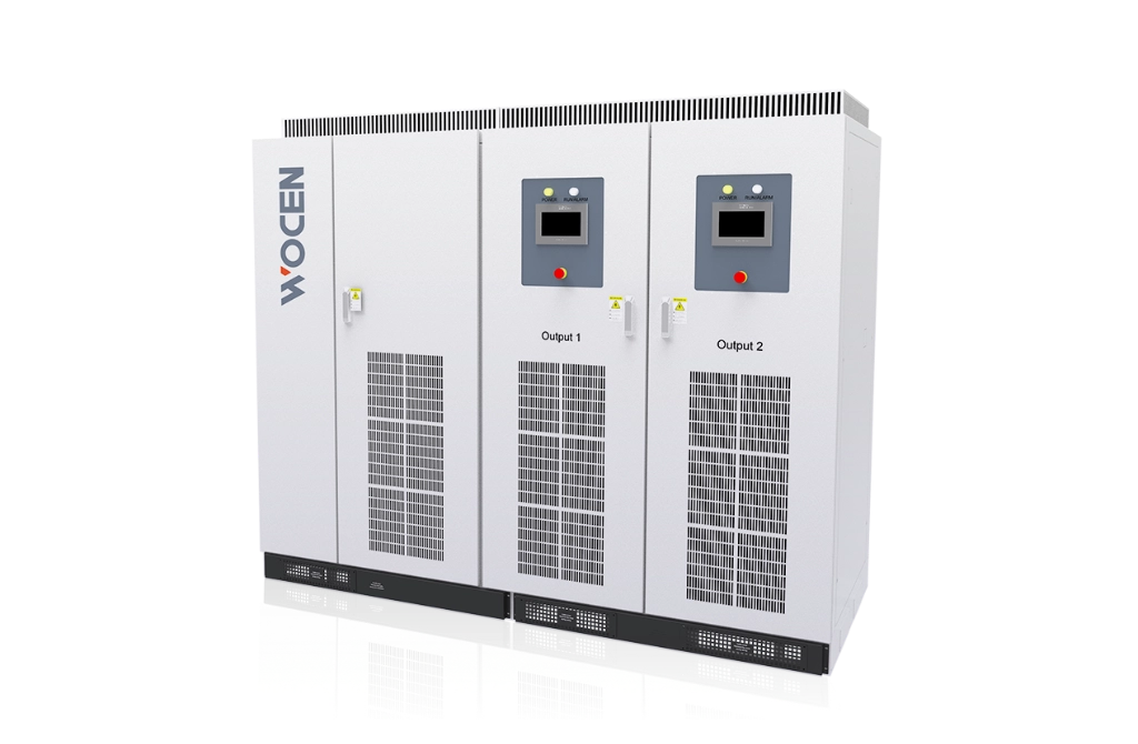
The EVWB Series Bidirectional DC Test Power Supply enables two-way energy flow, delivering power to the DUT and feeding energy back to the grid to reduce energy consumption, space, and operating costs.
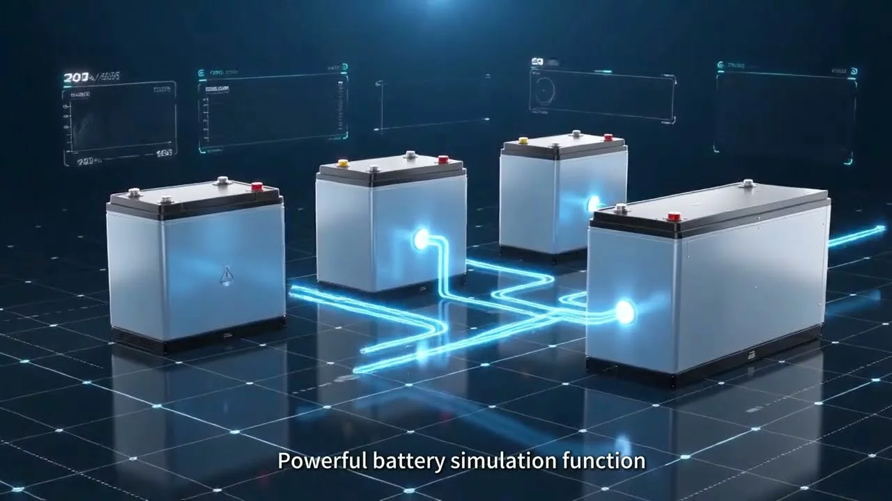
It features five built-in battery models, IV curve preview, user-defined battery models, and parallel operation for flexible power expansion.
Ideal for R&D, type testing, reliability testing, and production line testing of electric motors and related products.
Enables bidirectional energy flow across the full power range, allowing regenerative energy from EV motor testing to be fed back to the grid for improved energy efficiency.
02
Multiple Operating Modes
Supports Constant Voltage (CV), Constant Current (CC), and Constant Power (CP) modes.
03
Fast Transient Response
Delivers rapid response to dynamic load changes.
04
High-Precision Digital Control
High-speed digital control technology achieves output accuracy of ≤0.1% F.S.
Provides intuitive operation, clear display, and convenient human-machine interaction.
07
Multiple Communication Interfaces
Supports remote operation, unattended operation, and integration into automated test systems.
08
Automatic Line Voltage Compensation
Automatically compensates for voltage drops caused by cable losses.
09
High-Reliability Components
Uses high-quality components from leading domestic and international brands to ensure reliable operation.
10
Modular Design
Modular architecture simplifies maintenance and improves system flexibility.
11
Integrated Cooling Design
Optimized cooling channels ensure low temperature rise, stable operation, and extended service life.
Models & Specifications
Model
Rated Power
Peak Power
Output Voltage
Rated Voltage
Rated Current
Peak Current
Size(W×H×D)
EVWB-050-1000
50kW
75kW
24 ~ 1000V
250V
±200A
±300A
800×1800×980mm
EVWB-080-1000
80kW
120kW
24 ~ 1000V
267V
±300A
±450A
800×1800×980mm
EVWB-160-1000
160kW
208kW
24 ~ 1000V
320V
±500A
±650A
1200×2000×1080mm
EVWB-200-1000
200kW
260kW
24 ~ 1000V
400V
±500A
±650A
1200×2000×1080mm
EVWB-250-1000
250kW
325kW
24 ~ 1000V
417V
±600A
±780A
1800×2000×1080mm
EVWB-300-1000
300kW
390kW
24 ~ 1000V
500V
±600A
±780A
1800×2000×1080mm
EVWB-400-1000
400kW
520kW
24 ~ 1000V
500V
±800A
±1040A
2200×2000×1200mm
EVWB-500-1000
500kW
650kW
24 ~ 1000V
500V
±1000A
±1300A
2200×2000×1200mm
* Note :1) Output voltage can be selected 24~800V or 24~1200V
2) Rated current, peak current, peak power can be customized according to customer requirements
Technical Specifications
Category
Item
Parameter
AC characteristic
Input mode
3-phase 3-wire +PE
Voltage
AC380V ±10%
Frequency
50Hz ±5Hz
Power factor
≥0.99
Total current harmonic
≤3%
DC characteristic
Output accuracy
≤±0.1%FS
Source effect
≤0.1%FS
Load effect
≤0.1%FS
Ripple (Vrms)
≤0.2%FS
Response time
≤3mS (10%~90% sudden loading)
Feedback characteristic
Alternating current voltage
AC 342V~420V(Allowable voltage range)
Ac frequency
45Hz~55Hz(Allowable grid frequency)
Power factor
≥0.99
Total harmonic content
≤3%
Switching timer
≤6mS(+90%~-90% switching)
Feedback power
Supports full scale power feedback
Communication interface
RS485, CAN, LAN
Safety feature
Insulation resistance
≥20MΩ
Voltage resistance
2000VDC test 60S, no flashover, breakdown
Ground resistance
≤100mΩ
Noise
≤65dB
Protection grade
IP21 (Indoor)
Cooling mode
Forced air cooling
Working environment
Ambient temperature
−10~45℃
Ambient humidity
10%~90%(no condensation)
Altitude
≤2000m
Optional Functions
Distribution box PDU: to achieve the load terminal wiring is convenient and other functions, conducive to on-site system integration and improve security.
Release device PDSB: When the grid fails or the power supply is abnormal, it can effectively prevent the damage of the backfilling energy to the test equipment.
Capacitor cabinet: In order to meet the needs of smaller voltage fluctuations, in order to achieve or even exceed the dynamic characteristics of imported equipment.
Insulation monitoring function: online real-time monitoring of the output positive/negative electrode to the ground insulation impedance, to ensure the safety of equipment electricity.
Applications
Electric Vehicle Motor Testing
Electric Vehicle Motor Controller Testing
Electric Vehicle Powertrain Testing
Electric Vehicle Testing
Electric Vehicle DC-DC Converter Testing
Hybrid Vehicle Generator Testing
Bidirectional DC Power Supply Operation
Enables bidirectional energy flow across the full power range. Supports Constant Voltage (CV), Constant Current (CC), and Constant Power (CP) modes, with adjustable output voltage, current, and power parameters.
In CV mode, the DC output voltage operates according to the preset value. When the DC port output or input current exceeds the configured source/load current limit, the system switches to CC mode, where the output and input current can be adjusted independently through the source/load current settings. The port voltage is then determined by the external source or load.
When the external power exceeds the configured source/load power limit, the system enters CP mode. The operating power can be adjusted through the source/load power settings.
Battery Simulation
1) Battery Type Mode
Users can select from five built-in battery types: LMO, LCO, LiFePO₄, NMC, and lead-acid. The number of cells in series and parallel and the initial SOC can be configured. The IV curve can be previewed before starting the simulation.
2) Custom Battery Mode
Users can define battery characteristics and create customized IV curves. Up to 5 custom IV curve profiles can be stored and recalled for operation when required.
During battery simulation, the system dynamically generates and displays the IV curve based on SOC changes. SOC, charging/discharging status, output voltage, output current, and output power can be monitored in real time.
DC Programming
Provides Step and Ramp programming modes. Each programming mode supports up to 10 programmable profiles, with each profile containing up to 50 data sets.
Emergency Stop
Supports both local and external emergency stop controls. In emergency situations, such as motor runaway, the power output can be quickly shut down through the emergency stop switch on the control panel or an external emergency stop switch, helping prevent damage to the customer's equipment.
Line Voltage Compensation
Software compensation: Users can configure the line resistance (output cable impedance), and the system automatically compensates for output voltage drops based on the configured value.
Self-Discharge Function
Self-discharge disabled: After receiving a stop command, the system maintains the current output voltage and quickly disconnects the output.
Self-discharge enabled: After receiving a stop command, the system does not immediately disconnect the power. Instead, it rapidly reduces the output voltage to below a safe level before disconnecting the output.
Self-Diagnosis & Protection
Provides comprehensive protection against input overvoltage/undervoltage, overfrequency/underfrequency, overcurrent, and phase loss. Output protection includes overvoltage/undervoltage, overcurrent, overload, overtemperature, reverse polarity, and short circuit, as well as DC bus overvoltage/undervoltage and IGBT overcurrent protection.
The system continuously monitors operating parameters and automatically diagnoses abnormal conditions. In the event of a fault, it rapidly disconnects the main circuit to help prevent damage to internal components and ensure safe and reliable operation.
Communication
Standard communication interfaces include RS485, Ethernet, and CAN. The system supports connection to a PC for remote operation, unattended operation, and integration into automated test systems.
Users can start or stop the power supply, configure operating parameters, and monitor operating status, real-time parameter values, and alarm information through the communication interfaces. DBC files are available.
Black Box Function
Automatically stores electrical operating data before and after an alarm event, providing reliable information for fault analysis and troubleshooting.
Pre-Alarm Parameter Settings
Users can configure upper and lower pre-alarm thresholds for voltage, current, and power, with corresponding warning prompts according to specific operating conditions.
Output Parameter Limits
Upper limits can be configured for output voltage, current, and power settings. Users can modify these limits according to their requirements, helping prevent equipment damage caused by incorrect operation during different testing stages.
Temperature Monitoring
Provides real-time temperature monitoring of critical components, including IGBT modules, transformers, and reactors, to ensure safe and stable system operation.
Intelligent Fan Speed Control
Based on the temperature of internal critical components, the cooling fans automatically operate in three modes: off, half speed, and full speed. This reduces operating noise while improving overall system efficiency.
DC High-Voltage Output Relay Control
The DC output is controlled by a relay, enabling convenient and flexible remote control of the power supply.
Modular Design
1) Modular Power Architecture The core power units of the bidirectional DC test power supply adopt a modular design. The PWM rectifier and bidirectional DC/DC converter use standardized modules, allowing a faulty power unit to be quickly replaced.
2) Standardized Manufacturing The manufacturing process of functional modules is standardized to ensure consistent product quality and reliable performance.
3) Laminated Busbar Design The laminated busbar design effectively reduces circuit inductance and improves overall system reliability.
Segmented Overload Protection
Current Range
Power Range
Operating Time
Ie ≤ I ≤ 1.1 × Ie
Pe ≤ P ≤ 1.1 × Pe
240 s
1.1 × Ie ≤ I ≤ 1.2 × Ie
1.1 × Pe ≤ P ≤ 1.2 × Pe
120 s
1.2 × Ie ≤ I ≤ If
1.2 × Pe ≤ P ≤ Pf
60 s
Ie: Rated current If: Peak current Pe: Rated power Pf: Peak power