HomeProductsRegenerative Electronic Load

Regenerative Electronic Load

EVWR Series

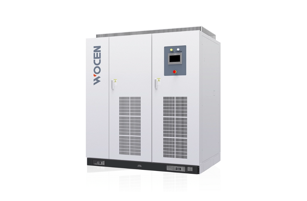
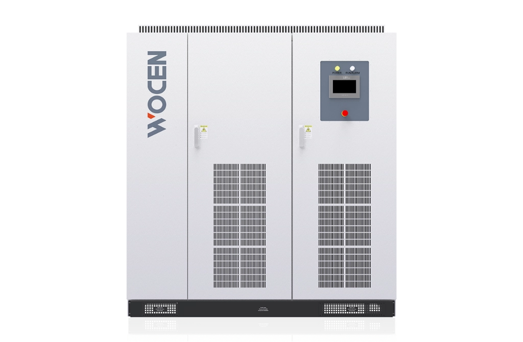
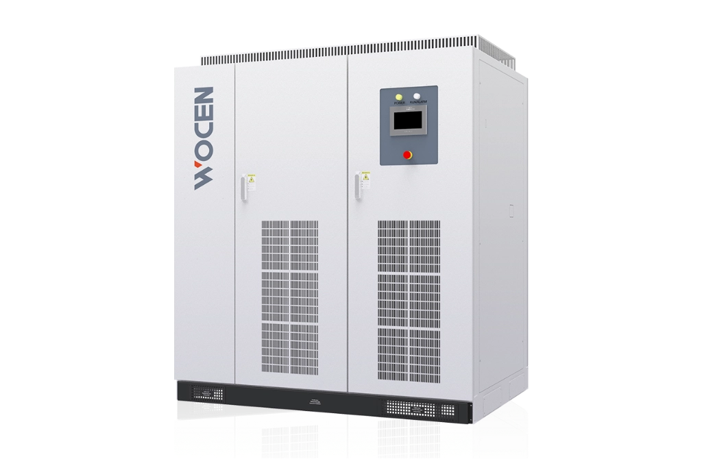
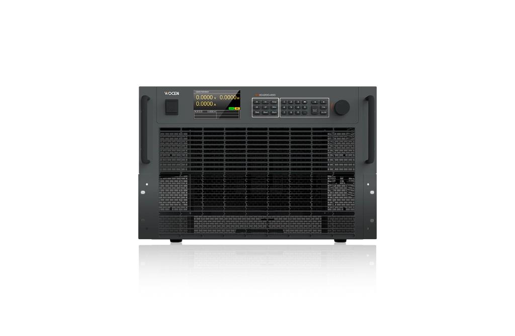
The EVWR Series Regenerative Electronic Load is designed for fuel cell engine testing, fuel cell DC/DC converter testing, charging pile aging tests, and other high-power test applications.

With four-quadrant PWM rectification, bidirectional buck conversion, and fully digital control, it delivers up to 100% energy regeneration, high accuracy, fast transient response, and high efficiency, while reducing grid pollution. Multiple communication interfaces and comprehensive protection functions ensure reliable and flexible testing.

Voltage accuracy

≤ ±0.05%FS

Response time

≤10ms(10%–90% sudden loading)

Current accuracy

≤ ±0.1%FS

Power resolution

0.01kW

Share:

  • Product Description

  • Product Features

Key Advantages

  • 01
    Four-Quadrant Operation

    Enables full-power bidirectional energy flow for stable, reliable, and energy-efficient operation.

  • 02
    Multiple Operating Modes

    Supports constant resistance (CR), constant voltage (CV), constant current (CC), and constant power (CP) modes.

  • 03
    Fast Transient Response

    Responds rapidly to dynamic load changes for accurate and stable testing.

  • 04
    High-Precision Digital Control

    Advanced high-speed digital control technology delivers output accuracy of up to 0.1%.

  • 05
    High Power Quality and Efficiency

    PWM rectification technology achieves a power factor of up to 0.99, input harmonics below 3%, and efficiency above 93%.

  • 06
    Automatic Voltage Drop Compensation

    Automatically compensates for line voltage drops to maintain stable output performance.

  • 07
    10-Inch Touchscreen

    Provides an intuitive interface for convenient operation, monitoring, and parameter setting.

  • 08
    Programmable Parameters

    Output and protection parameters can be freely configured to meet the testing requirements of different devices.

  • 09
    High Reliability

    Uses high-quality components from internationally recognized brands, including LEM and Infineon, to ensure reliable long-term operation.

  • 10
    Modular Design

    Modular architecture simplifies maintenance and reduces service time and costs.

Models & Specifications

Model number

Rated power

Voltage range

Rated current

Model number

Rated power

Voltage range

Rated current

EVWR-060-600-600

60kW

10~600V

600A

EVWR-120-1000-600

120kW

10~1000V

600A

EVWR-060-600-800

60kW

10~600V

800A

EVWR-120-1000-800

120kW

10~1000V

800A

EVWR-060-600-1000

60kW

10~600V

1000A

EVWR-120-1000-1000

120kW

10~1000V

1000A

EVWR-060-1000-600

60kW

10~1000V

600A

EVWR-150-800-600

150kW

10~800V

600A

EVWR-060-1000-800

60kW

10~1000V

800A

EVWR-150-800-800

150kW

10~800V

800A

EVWR-060-1000-1000

60kW

10~1000V

1000A

EVWR-150-800-1000

150kW

10~800V

1000A

EVWR-080-800-600

80kW

10~800V

600A

EVWR-150-1000-600

150kW

10~1000V

600A

EVWR-080-800-800

80kW

10~800V

800A

EVWR-150-1000-800

150kW

10~1000V

800A

EVWR-080-800-1000

80kW

10~800V

1000A

EVWR-150-1000-1000

150kW

10~1000V

1000A

EVWR-080-1000-600

80kW

10~1000V

600A

EVWR-200-800-600

200kW

10~800V

600A

EVWR-080-1000-800

80kW

10~1000V

800A

EVWR-200-800-800

200kW

10~800V

800A

EVWR-080-1000-1000

80kW

10~1000V

1000A

EVWR-200-800-1000

200kW

10~800V

1000A

EVWR-100-800-600

100kW

10~800V

600A

EVWR-200-1000-600

200kW

10~1000V

600A

EVWR-100-800-800

100kW

10~800V

800A

EVWR-200-1000-800

200kW

10~1000V

800A

EVWR-100-800-1000

100kW

10~800V

1000A

EVWR-200-1000-1000

200kW

10~1000V

1000A

EVWR-100-1000-600

100kW

10~1000V

600A

EVWR-250-800-600

250kW

10~800V

600A

EVWR-100-1000-800

100kW

10~1000V

800A

EVWR-250-800-800

250kW

10~800V

800A

EVWR-100-1000-1000

100kW

10~1000V

1000A

EVWR-250-800-1000

250kW

10~800V

1000A

EVWR-120-800-600

120kW

10~800V

600A

EVWR-250-1000-600

250kW

10~1000V

600A

EVWR-120-800-800

120kW

10~800V

800A

EVWR-250-1000-800

250kW

10~1000V

800A

EVWR-120-800-1000

120kW

10~800V

1000A

EVWR-250-1000-1000

250kW

10~1000V

1000A

* Note: The maximum power of a single machine is 500kW, the maximum current of a single machine is 1200A, it can support parallel function and customization.

Technical Specifications

Category

Item

Specification

Working mode

Constant voltage, constant current, constant power, constant resistance

Voltage accuracy

≤ ±0.05%FS

Voltage resolution

0.01V

Current accuracy

≤ ±0.1%FS

Current resolution

0.01A

Current ripple

≤0.1%FS

Power resolution

0.01kW

Response time

≤10ms(10%–90% sudden loading)

AC characteristic

Output AC voltage

Three-phase three wire +PE, 380Vac±10%

AC characteristic

Output frequency

50Hz±5Hz

AC characteristic

Feedback function

Full power range energy feedback

AC characteristic

Current distortion

<3%

AC characteristic

Power factor

≥0.99

AC characteristic

Overall efficiency

≥93%

Communication and operation

Man-computer interface

Touch screen

Communication and operation

Communication interface

RS485, CAN, LAN

Communication and operation

Communication response speed

10mS

Protection

Protection

DC over voltage/over current/overpower, AC phase loss/over voltage/over current/over power, IGBT device over temperature

Security features

Insulation resistance

≥20mΩ

Security features

Voltage resistance

2000VDC test 60S, no flashover, breakdown

Security features

Ground resistance

≤100mΩ

Security features

Protection Class

IP21(indoor)

Working environment

Ambient temperature

−10–45℃

Working environment

Ambient humidity

10–90%(no condensation)

Working environment

Altitude

≤2000m

Applications

  • Electric vehicle motor testing

  • Charging Pile Test

  • Fuel Cell DCDC Test

  • Fuel Cell Test System

  • Electric Vehicle DCDC Test

Four Operating Modes
The DC side supports four operating modes: Constant Current (CC), Constant Power (CP), Constant Voltage (CV), and Constant Resistance (CR). When the fuel cell stack (or engine) is operating normally, loading tests can be performed manually or automatically, with multiple operating modes available during discharge testing.

Adjustable Current Ramp Rate
In Constant Current (CC) mode, the current rise and fall rates can be adjusted to meet different discharge current ramp requirements.

Low-Voltage, High-Current Operation
The system provides stable operation under low-voltage and high-current conditions, making it suitable for discharge testing of fuel cell stacks (or engines) with low-voltage, high-current characteristics.

Self-Diagnostics and Protection
The system provides comprehensive protection functions, including DC-side reverse-polarity protection to prevent damage caused by incorrect connections between the fuel cell stack (or engine) and the load. AC-side protection includes phase loss, overvoltage, undervoltage, and short-circuit protection, while DC-side protection covers overvoltage, overcurrent, and overpower conditions. IGBT and magnetic component temperatures are also monitored in real time.

During testing, if a load fault occurs or the fuel cell stack (or engine) voltage drops to zero, the electronic load automatically disconnects from the stack to ensure safe operation.

Communication Functions
RS485 and CAN communication are provided as standard, with Ethernet available as an option. The system can connect to a PC for remote operation, unattended testing, and integration into automated test systems. Through the communication interface, users can start or stop the system, configure operating parameters, and monitor operating status, measurement data, and alarm information in real time.

Emergency Stop
The system features both local and external emergency-stop functions. In emergency situations, such as uncontrolled motor operation, the power output can be stopped immediately using the emergency-stop switch on the control panel or an external emergency-stop signal, helping protect the customer's equipment.

Current Programming
Up to 10 programmable profiles can be configured, with each profile containing up to 20 steps. Each step includes a duration and target current. Users can configure ramp or step operation modes, cycle counts, and the number of operating steps to meet different test requirements.

Soft-Start / Current Buffering
The startup buffering function ensures that the internal capacitor voltage matches the external voltage before the main power circuit is connected. This helps prevent inrush current and minimizes impact on the normal operation of the fuel cell stack.

Black Box Data Recording
The black box function automatically records electrical parameters before and after an alarm event, providing reliable data for fault analysis and troubleshooting.

Online Insulation Monitoring
The system continuously monitors the insulation resistance between the positive/negative DC terminals and the chassis (ground), with Level 1 and Level 2 insulation alarms available for enhanced safety monitoring.

Communication Loss Monitoring
The system continuously monitors communication between the upper-level and lower-level controllers. A communication interruption automatically triggers a communication-loss fault.

Reverse-Polarity Protection Cabinet
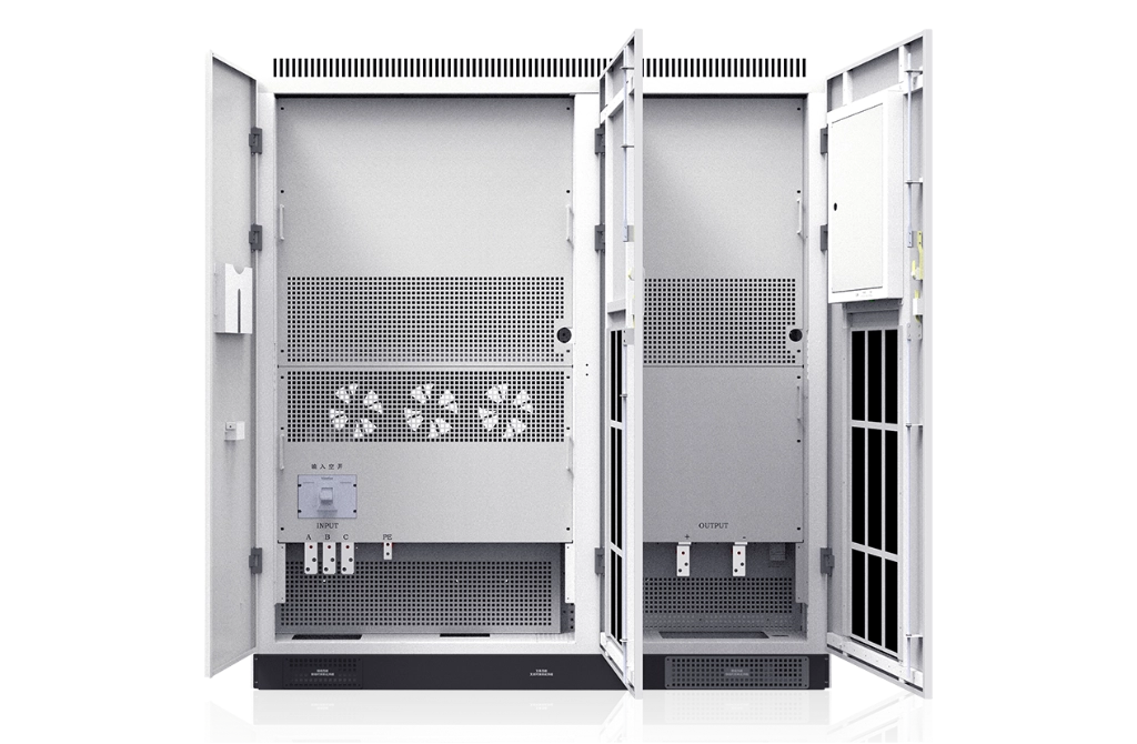
The system is equipped with a dedicated reverse-polarity protection cabinet with built-in cooling fans. The cabinet requires a 220 V AC power supply provided by the customer.


Related Products


Customizes photovoltaic and battery energy storage solutions for global customers.
WhatsApp

Leave a message!

Leave a message!